2017 China New Design PTFE Envelope EPDM Gasket to Angola Factories
2017 China New Design PTFE Envelope EPDM Gasket to Angola Factories Detail:
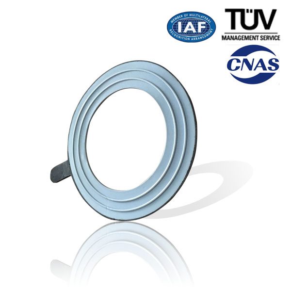
PTFE envelope EPDM gasket utilizing PTFE jacket have become popular for use in severely corrosive services because of its low min. Seating stress, excellent creep resistance, high deformability and choice of a variety of filler materials to assure optimum performance on any specific application.
Product Feature:
l Virtually 100% chemically resistance
l Temperature resistance: -200~+260℃
l Pressure resistance: 4Mpa
Application
PTFE envelope gaskets are widely used in food and process industrial where contamination of the medium can not be permitted. Suitable for medium strong alkalis, cryogenic fluids, oxygen, chlorine gas etc.
Product detail pictures:
Related Product Guide:
A Look at the Molded Gasket
Useful Tips For Installing The Teflon Envelope Gasket
2017 China New Design PTFE Envelope EPDM Gasket to Angola Factories, The product will supply to all over the world, such as: , , ,
High speed servo rotary cutter for extruded plastic profile.