Good Wholesale Vendors Spiral Wound Gasket-CGI to Holland Factory
Good Wholesale Vendors Spiral Wound Gasket-CGI to Holland Factory Detail:
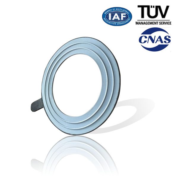
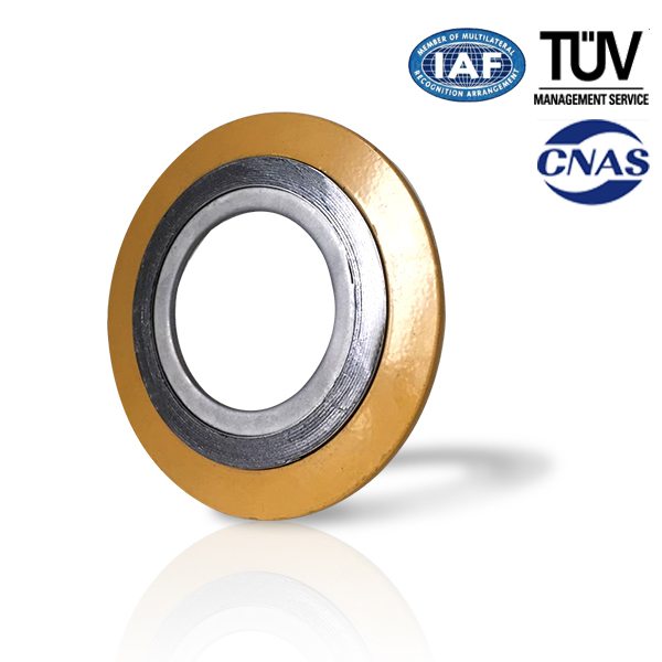
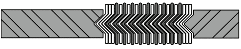
Spiral wound gasket consists of “V-shape”(or”W-shape”)metal tape and nonmetal tape, which are overlapped each other and wound continuously.To fasten the metal tape,both its start point and end point are tack welded.
Feature
Wide Scope of acceptable working conditions. Can be used under high temperature, high pressure and ultra-low temperature or vacuum conditions. Change the combination of the gasket materials is to tackle the chemical corrosion problem of diverse media toward the gasket.
Not very rigid requirements to the surface precision of the flange. May be used to seal flanges with rough surface
Easy installation and handy use.
Excellent Sealability
Products Type
Technical Data Sheet
|
Product&Type |
Size(mm) |
Temperature(℃) |
Pressure(Mpa) |
|
Spiral Wound Gasket filled with Graphite
|
φ16~φ3200 |
(In Oxidizing Environment )-240~+550℃;(In non-Oxidizing Environment)-240~+870℃ |
(Under hot water, oil etc. )30 Mpa; (Under vapor oil, gases etc.)20 Mpa |
|
Spiral Wound Gasket filled with Asbestos
|
φ16~φ3200 |
-150~+450℃ |
15 |
|
Spiral Wound Gasket filled with PTFE
|
φ16~φ3200 |
-200~+250℃ |
15 |
Application Area
The Spiral Wound Gaskets are mainly used in valves &pipes, pressure vessel, condenser, heat exchanger flanges in oil, chemical, metallurgy, vessel and mechanical industries.
Product detail pictures:

Related Product Guide:
A Look at the Molded Gasket
O-Ring Sizes for Industrial Applications
Good Wholesale Vendors Spiral Wound Gasket-CGI to Holland Factory, The product will supply to all over the world, such as: , , ,
Unfortunately i could not show how i weld the parts together i don’t have a bi-pod for my camera , but i have tried to explain in English what i have done as best as i can , If your have any questions about the parts or the design please do not hesitate. I would also be happy to upload a video for people that would like a view at a specific part on the pump.
Please check for Part 2 the whole pump assembly i ll do another explanation , and part 3 having the two ram-pumps pump together. thank you for watching
In this second part series, We continue with the removal of the hydraulic saginaw Steering gearbox. Seens from our first part series https://www.youtube.com/watch?v=EaK_pc95Poo
have additional information for a complete understanding and How-to procedure. Here we show you the appropriate tools, method and technique to remove the hydralic steering box from the Nissan D22 frame rail. Removal of the Power-assist steering gearbox to service the pitman arm shaft oil,dirt and water seal. Why it is necessary to remove the saginaw steering box to replace the pitman arm shaft seal. Also discuss, what cause the hydralic power steering system pump to create noise and cavitate. Not your avarage repair, labour intense and time consuming. We recommend viewing of this video and seek professional help toward solving the pitman arm oil leak remedy. Since this oil leak exist at the front of the vehicle. The oil will most likely spray itself on to rubber parts located under the vehicle carriage. Rubber parts cover or coated by power-steering oil will soon become deform and destroy which will lead to more failure with system and control parts like body rubber bushing, control arm and stabilizer bar insolator,axle CV joint boot, Ball joint rubber seal and a dirt build of oil and soil. Always, water and soap pressure wash the undercarriage of the vehicle becore and after work-order procedure.
Here is another video describing the identical application in a different automotive make and model.
Thank you for your viewership plus you just learn something new that cane be share with other so please comment with your question, concern and your knowledge. You should also subscribe if you find interest and common ground.
Checking Hydraulic System.
Before starting, check belt tension, driving pulley and tire pressure.
1. Set Tool. Open shut-off valve, then bleed air. Refer to PS-8,
“Bleeding Hydraulic System” .
2. Run engine at idle speed or 1,000 rpm.
3. Bring power steering fluid up to adequate operating tempera-
ture. [Make sure temperature of fluid is approximately 60 to
80°C (140 to 176°F).]
WARNING:
Warm up engine with shut-off valve fully opened. If engine
is started with shut-off valve closed, fluid pressure in the
power steering pump increases to maximum. This will raise
fluid temperature abnormally.
4. Check pressure with steering wheel fully turned to left and right positions while idling at 1,000 rpm.
CAUTION:
Do not hold the steering wheel at full lock position for more than 15 seconds.
● If pressure reaches maximum operating pressure, system is OK.
● If pressure increases above maximum operating pressure, check power steering pump flow control
valve. Refer to PS-17, “Components” .
5. If power steering pressure is below the maximum operating pressure, slowly close shut-off valve and check pressure again.
CAUTION:
Do not close shut-off valve for more than 15 seconds.
● If pressure increases to maximum operating pressure, gear is damaged. Refer to PS-17, “Compo-nents”PS-15, “Removal and Installation” .
● If pressure remains below maximum operating pressure, pump is damaged. Refer to PS-17, “Compo-nents” .
6. After checking hydraulic system, remove Tool and add fluid as necessary. Completely bleed air out of sys-tem. Refer to PS-8, “Bleeding Hydraulic System” .
Power steering pump maximum operating pressure: 7,551 – 8,336 kPa (77 – 85 kg/cm2 , 1,095 – 1,209 psi)


